Manual MosaicThe manual mosaic tool for PCI Geomatica allows the user to mosaic individual image files or to edit images and/ or cutlines in files which were created in the automatic mosaic tool.. These are some basic steps to allow the user to mosaic a series of orthorectified images of Amberg, Germany.
Project Setup 1 . Open Geomatica Orthoengine 2014 application by clicking the airplane symbol ( Figure 1). 
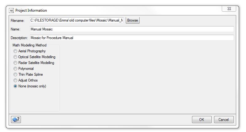
Figure 1 : Project set up
2 . From the OrthoEngine toolbar select file and then new.
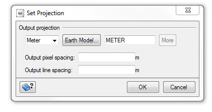
a) Then name your project and give it a description (Figure 2) b) Select none (mosaic only) as the math modeling method (Figure 2) c) In the following set projection window enter the output projection and resolution (Figure 3) Note: if you select cancel the output projection and resolution will be selected from the first image which is added.
Adding Images to the Project
1 . From the Processing step drop down menu select Image Input 2 . Click the open a new or existing image button ( file folder) 3. In the open image dialog box select add image (Figure 4). 4. Add images from the appropriate file. The images should be preferably tif format. Note: If the digital images are acquired from several sources and differ in size, format, resolution and number of bands this increases the complexity of mosaicking images (Selivonenko et al., 2000). The image will not load from the file folder if they have varying components such as spatial resolution. 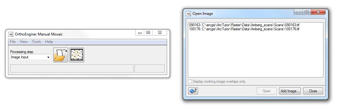
Figure 4: Add input images for mosaic project
Mosaicking
1 . From the Processing step drop down menu select Mosaic (Figure 5) 2. Click define mosaic area from the Mosaic toolbar 3. In the define Mosaic window, click the browse button and locate the folder where you would like to save your mosaic. and give it a name. 4. Uncheck the create later box to create the mosaic immediately. 4. Click Ok when you are satisfied with the parameters. 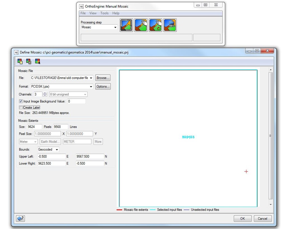
Figure 5 : Define mosaic area
The Mosaic Tool
1 . Click Manual Mosaic from the Mosaic toolbar 2. Right click on "cutline", "Label", "Local Mask" or "Match area" from each image in the file tree. 3. Collect cutlines for each image (optional). If you do not collect a cutline for each image then the entire file will be used in the mosaic. 4. Select the first image in the file tree. 5. Click the new cutline icon with polygon, rectangle and ellipse options 6. Place the curser at the location where the cutline should be collected. 7. Draw a polygon around the portion of the image which should be included in the mosaic.. Be sure to include ideal portions of the image and keep the overlapping sections (Figure 6). a) hit the enter key or double click to close cutline b) Use undo toolbar to remove a bad cutline. This toolbar is really helpful to make corrections. Note: To make the seams between images less visible, select features which are consistent in tone and texture, low to the ground, uniform in appearance such as roadways and river edges. c) Avoid: buildings, large bodies of water, areas which look similar in colour and texture such as forest and cultivated land. 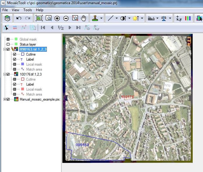
Figure 6: Manual mosaic tool ( defining cutlines)
8. Cutlines can be edited by clicking the cutline editing toolbar icon. The editing tools will become available after selecting the cutline with the find tool in the toolbar,.
9. Collect the cutlines for the remaining images using the above steps Colour Balancing This process can be completed in two ways Manual Area or Overlap Area 1 . To complete the colour balance select an image from the file tree and click the New Match Area icon. 2. Draw the match areas (where the images overlap) in the viewer (Figure 7). 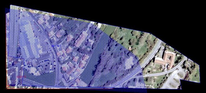
Figure 7: Drawing the match area
3. Click the Color Balancing icon pull down menu.. Choose either Manual Area and Overlap Area.
4. The blend width can be adjusted using the cutline blend width option. This determines the number of pixels on either side of the cutline that are used to blend the seam. In the main viewer, right mouse click on the cutline for each file and select “Set Blend Width”. The value used will vary depending on the input images but a value of 0 – 5 is generally used. This makes the seam more obscure. Creating the Mosaic 1. In the Mosaic Tool window, select the images which should be included in the mosaic. 2. Click on the add Images to Mosaic Icon (Figure 8). 3. To reprocess any of the images right click on the image name under the mosaic file and select “Reprocess”. 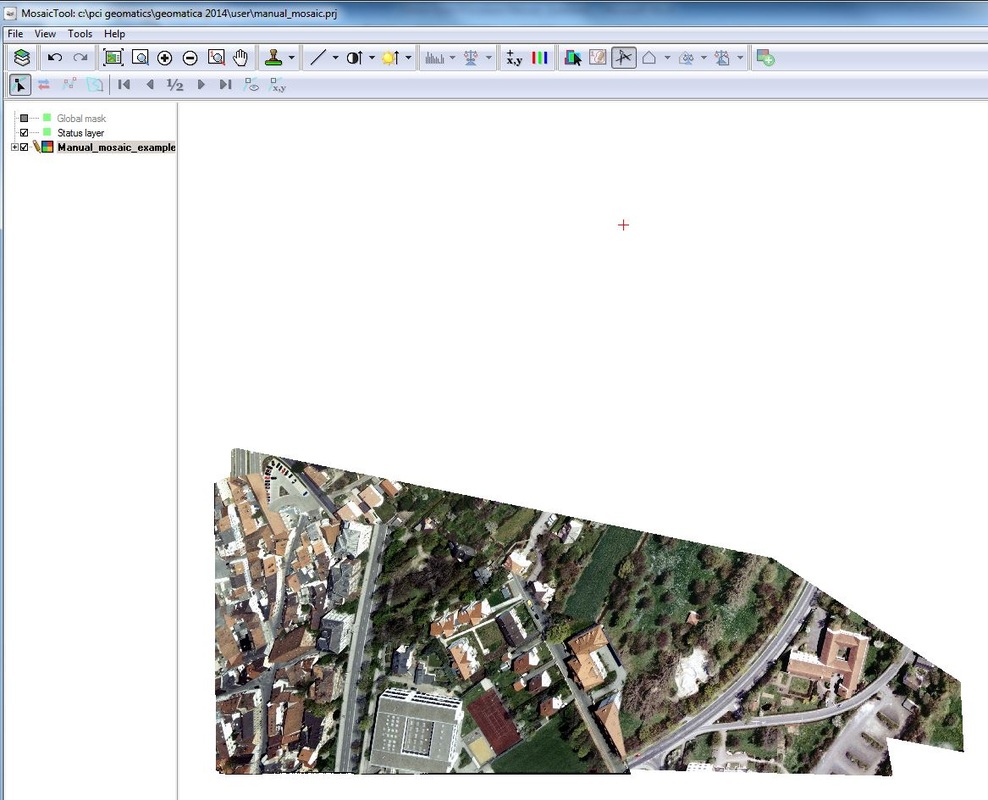
Figure 8 : The final mosaic after the two images were added
Close Up of Cutlines
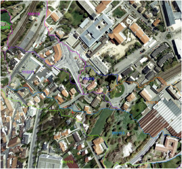
Figure 9: A close up of the cutlines generated using Manual Mosaic using all 12 images.
The Final Manual Mosaic
The following is the final output using all 12 images in the dataset. The above steps were completed using only two images (Figure 10), 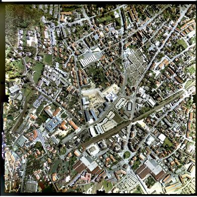
Figure 10: The Final Mosaic using all 12 images
|
ReferencesPCI Geomatics. "Geomatica OrthoEngine V10.3 Tutorial Manual Mosaicking." 2014. pp.1 -15. Web. 15 March. 2015. <http://www.pcigeomatics.com/pdf/geomatica/tutorials/Manual_Mosaicking.pdf>.
Selivonenko, A., Prabakar, N., Rishe, N., & Davis-Chu, D. L. (2000, November). Dynamic Mosaicking of Heterogeneous Digital Images. In ISCA 2nd International Conference On Information Reuse And Integration (pp. 86-90) http://cake.fiu.edu/Publications/selivonenko+al-00-DM.DynamicMosaicking.IRI-2000.prabu.camera_ready.PDF |